


UML sequence diagrams are essential tools for visualizing the flow of interactions between objects in a system. They show how components work together over time to complete a task—such as processing an online order, authenticating a user, or handling a payment. These diagrams are part of the Unified Modeling Language (UML), a standardized modeling language used in software engineering to design and document systems.
Unlike class diagrams that focus on structure, sequence diagrams emphasize time-ordered communication. They help developers, architects, and stakeholders understand how objects collaborate, when messages are sent, and how control flows through a system. This makes them especially useful during the design phase of software development, where clarity about system behavior is crucial.
Core Elements of a Sequence Diagram
A sequence diagram is built from several key components that work together to represent system behavior:
- Lifelines: These are vertical dashed lines that represent the existence of an object or actor over time. Each lifeline starts at the top and extends downward, showing the object’s lifecycle during the interaction.
- Actors: External entities—like users, other systems, or hardware devices—interact with the system. In diagrams, actors are typically shown as stick figures. They initiate or respond to actions within the system.
- Messages: Horizontal arrows between lifelines represent communication. These can be synchronous (the sender waits for a response) or asynchronous (the sender continues without waiting). Messages are labeled with the method or action being called.
- Activation Bars: Thin rectangles on a lifeline indicate when an object is actively processing a message. They show the duration of an operation and help visualize the flow of control.
- Combined Fragments: These are boxes used to represent complex logic such as loops (
loop), alternative paths (alt), or optional steps (opt). They allow you to model conditional behavior, repetition, and concurrency in a structured way.
For example, in a login process, a user sends a login request to the system, the system verifies credentials, and then returns a success or failure message. A sequence diagram captures this flow clearly, showing the order of messages and the time sequence of events.
The Role of AI in Modern Sequence Diagram Design
Creating accurate and clean sequence diagrams can be time-consuming—especially when working with complex systems. Traditional methods often involve manually placing lifelines, drawing messages, and ensuring proper alignment. But with the rise of AI-powered modeling tools, this process has become faster and more intuitive.
One such platform is Visual Paradigm, a comprehensive visual modeling environment used by software architects and developers. It supports UML and other modeling standards and now includes an AI Ecosystem that leverages generative AI to automate diagram creation.
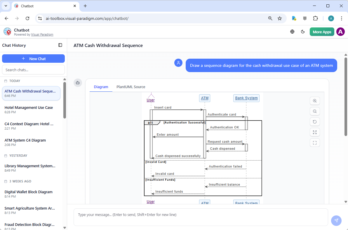
This AI system allows users to describe a scenario in plain English and instantly generate a sequence diagram. For instance, typing “A customer withdraws cash from an ATM” produces a diagram with the correct lifelines (Customer, ATM, Bank Server), messages (request withdrawal, verify funds, dispense cash), and activation bars.
The AI doesn’t just generate a basic sketch—it produces standards-compliant diagrams that follow UML conventions. This ensures consistency across teams and projects, and allows the diagrams to be imported into the full Visual Paradigm desktop application for further refinement.
How Visual Paradigm Enhances the Diagramming Process with AI
The AI-powered tools in Visual Paradigm offer several features:
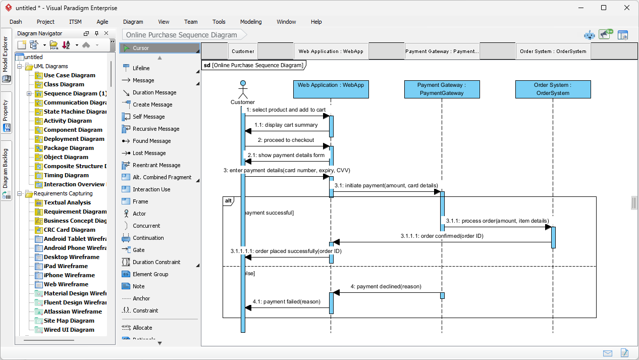
VP Desktop: AI Sequence Diagram Generation
integrates the AI sequence diagram generator directly into the professional modeling suite. This feature is particularly powerful for documenting intricate scenarios like an online purchase flow.
AI Chatbot
The first point of contact for many modern designers is the conversational interface. The Visual Paradigm AI Chatbot serves as a dedicated assistant that interprets user prompts to build comprehensive diagrams
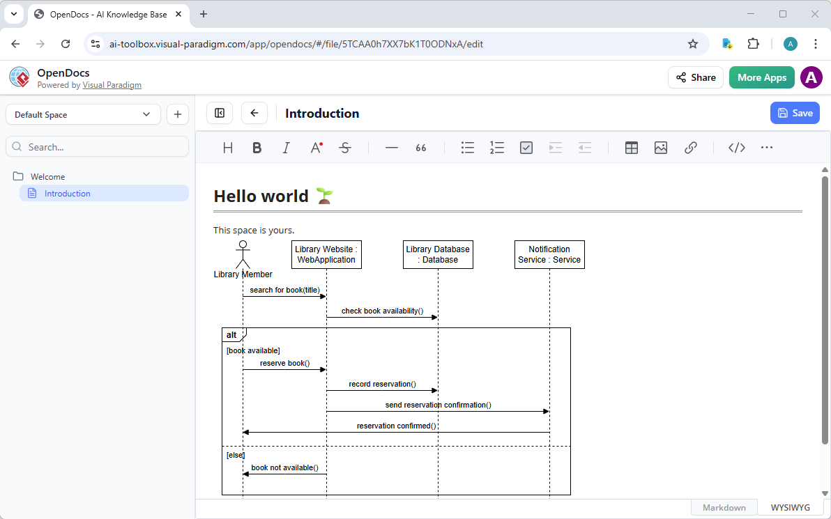
OpenDocs
Diagrams are great, but they shine brightest when they’re part of living documentation. That’s where OpenDocs comes in—Visual Paradigm’s knowledge management platform that feels like a supercharged Notion or GitBook, but with truly dynamic, editable visuals.
Step-by-Step AI Powered Apps
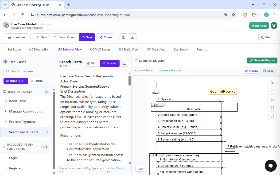
Beyond isolated diagrams, Visual Paradigm offers the Use Case Modeling Studio—a specialized web application designed for comprehensive requirements analysis. Within this environment, the “UC Behavior View” acts as the connective tissue between a use case description and its technical implementation. When a business analyst defines a use case, such as “Search Restaurants,” the studio allows them to generate an associated sequence diagram with a single click. This ensures that the behavioral model is always synchronized with the functional requirements.
Practical Example: Generating a Sequence Diagram
Let’s say you’re designing a system for a food delivery app. You want to model the process of placing an order. A simple prompt like:
“A customer places an order in a food delivery app. The app checks inventory, confirms the order, processes payment, and sends a confirmation to the customer.”
The AI would generate a sequence diagram with:
- Lifelines: Customer, App, Inventory System, Payment Gateway, Delivery System
- Messages: Place Order → Check Inventory → Confirm Order → Process Payment → Send Confirmation
- Activation bars showing when each system is active
- Combined fragments for error paths (e.g., out-of-stock items)
You can then refine it further by adding constraints or alternative flows, such as “if payment fails, notify customer and cancel order.”
Why Sequence Diagrams Matter Today
In modern software development, especially with microservices and distributed systems, understanding how components interact is critical. Sequence diagrams provide a clear, visual representation of these interactions, helping teams:
- Identify bottlenecks or race conditions
- Ensure proper error handling
- Communicate system behavior across teams
- Validate requirements before implementation
When combined with AI tools, the creation of these diagrams becomes less manual and more intuitive. The result is faster design cycles, fewer misunderstandings, and more reliable systems.
Final Thoughts
Sequence diagrams remain a vital part of software design, offering a clear view of how systems behave over time. With the integration of AI, creating these diagrams has become more accessible and efficient. Tools like Visual Paradigm’s AI Ecosystem help teams move from idea to diagram quickly, without sacrificing accuracy or standards.
For developers and architects looking to streamline their modeling workflow, leveraging AI-assisted UML tools can be a powerful step toward more efficient and effective system design.
- What is a Sequence Diagram? – Visual Paradigm UML Guide: Comprehensive introduction to UML sequence diagrams as interaction diagrams that model dynamic object collaborations over time, detailing purpose (capturing message sequences for use case scenarios or operations), key elements (lifelines, actors, messages: synchronous/asynchronous/call/return/create/destroy, activations, focus of control), combined fragments (alt, opt, loop, par, ref, etc.), notation, constraints, examples (e.g., hotel reservation), and best practices for modeling interactions above code level.
- How to Draw Sequence Diagrams in Visual Paradigm – Software Design Handbook: Practical, step-by-step tutorial on creating UML sequence diagrams in Visual Paradigm: identifying participants/objects, drawing lifelines and messages (synchronous, asynchronous, return, create/destroy), adding execution focus/iteration, using combined fragments (alt/opt/loop/par/ref), handling object creation/destruction, with examples like “Place Order” scenario (customer-order-stock interactions) and best practices for main/exceptional flows.
- AI-Powered Use Case to Activity Diagram Generator – Visual Paradigm: AI feature that automatically converts detailed textual use case descriptions (actors, preconditions, main/alternate/exception flows) into editable UML activity diagrams, detecting missing steps, suggesting improvements, analyzing flow quality, and supporting export with reports—focused on workflow visualization (no direct mention of sequence diagram conversion).
- UML Sequence Diagrams: Modeling Object Interactions – Software Ideas: Overview explaining sequence diagrams as interaction diagrams that illustrate message exchanges between objects/actors over time to model system behaviors, dynamic scenarios, and collaborations in UML.
- Sequence Diagrams – UML Diagrams.org: Technical reference on UML sequence diagram syntax, semantics, and usage: lifelines, messages, execution specifications, combined fragments, interaction occurrences, and examples for specifying interaction scenarios.
- Visual Paradigm: AI-Powered Modeling Platform: Comprehensive suite for UML/BPMN/SysML/ArchiMate diagramming, with AI-assisted generation, refinement, and collaboration across diagram types including sequence, class, activity, and more.
- The Evolution of UML: From Manual Drafting to AI-Powered Strategic Design – Diagrams AI: Article tracing UML’s progression with AI integration (e.g., in tools like Visual Paradigm), shifting from manual syntax focus to automated, conversational generation and refinement for strategic architecture.
- AI Deployment Diagram Generation in Visual Paradigm: Explores AI chatbot for generating UML deployment diagrams from text prompts (e.g., architectures for streaming/e-commerce), with stereotypes, iterative refinements, and desktop import—highlights broader AI support for 40+ diagram types (sequence implied in ecosystem).
- Comprehensive Review: Visual Paradigm’s AI Diagram Generation Features – Fliplify: Third-party analysis of AI tools for standards-compliant, fast diagram creation/refinement across UML types (including sequence), usability, conversational editing, and productivity gains.
- Enhanced AI Composite Structure Diagram Generation – Visual Paradigm Updates: Release notes on improved AI stability and detail for composite structure diagrams via chatbot, with support for natural language prompts, refinements, and extension to other UML types like sequence, class, and use case.
- Turning Scenarios into UML Sequence Diagrams with AI – YouTube Tutorial: Video guide demonstrating AI conversion of real-world scenarios into editable UML sequence diagrams, highlighting generation and refinement steps.
- Generate UML Class Diagrams from Text with AI – Visual Paradigm: Guide to AI-powered class diagram creation from natural language, with iterative prompts, layout, and export—principles applicable to similar dynamic diagrams like sequence.
- Generate UML Sequence Diagrams Instantly with AI – Visual Paradigm Blog: Details Visual Paradigm’s AI chatbot for instant sequence diagram creation from natural language scenarios (e.g., washing machine process), iterative refinements via conversation, and seamless import to Visual Paradigm for editing and enhancement.
- Enhanced AI Activity Diagram Support via Chatbot – Visual Paradigm Updates: Updates improving AI activity diagram quality (orphan removal, readable styling, desktop import), with broader implications for related dynamic UML diagrams like sequence in the AI suite.
- AI Activity Diagram Generation in Visual Paradigm Desktop – Updates: Release introducing desktop AI for generating activity diagrams from text/use cases/workflows (actions, decisions, parallels, exceptions), with intelligent layout—part of expanding AI capabilities that support sequence and other interaction diagrams.
 jick
jick- AI, AI Chatbot, UML
- March 9, 2026