


In the complex landscape of retail banking, operational efficiency is paramount. A loan application and approval process is not merely a sequence of events; it is a critical business pipeline that requires rigorous validation, risk assessment, and regulatory compliance. In this tutorial, we will dissect the architecture of a standard loan approval workflow using Visual Paradigm‘s Business Process Model and Notation (BPMN) tools.
This article moves beyond simple diagramming to explore the structural logic, swimlane organization, and decision-making nodes that define this financial process. We will demonstrate how to construct a robust process model that ensures data integrity from the initial customer submission to the final committee approval.
1. Architecting the Process: The Swimlane Concept
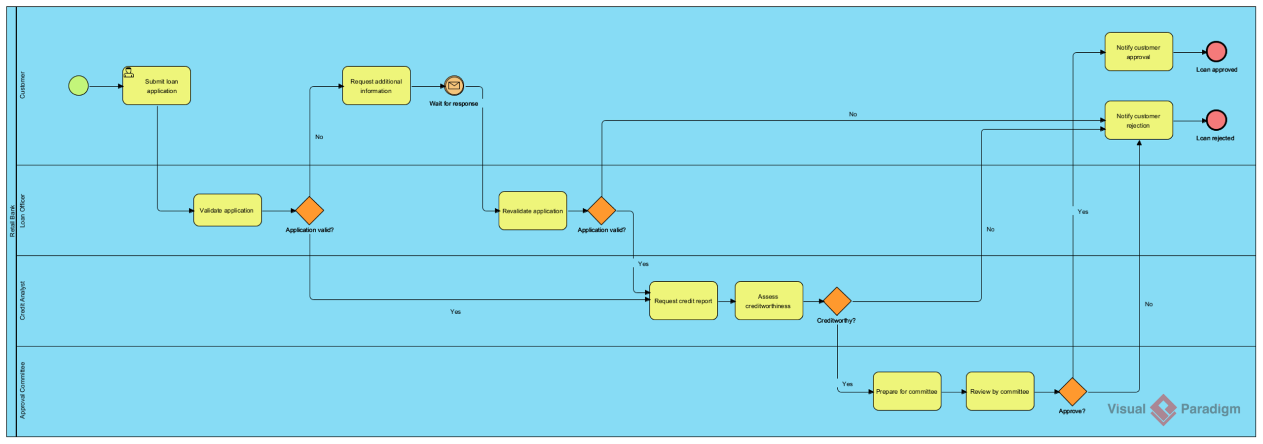
The foundation of a clear BPMN diagram is the organization of activities. In the diagram below, Visual Paradigm utilizes a Swimlane architecture. This visual metaphor divides the process into distinct responsibility areas, ensuring that every task is assigned to the correct actor.
- Customer: The external entity initiating the process. They are responsible for the primary actions of submitting the application and providing missing information.
- Loan Officer: The internal gatekeeper. This role handles the initial validation of the application and manages the revalidation loop if the application is incomplete.
- Credit Analyst: The technical evaluator. This lane focuses on the data-heavy task of assessing creditworthiness.
- Approval Committee: The executive decision-makers. This group performs the final review and issues the binding decision.
By visually separating these lanes, Visual Paradigm helps stakeholders identify bottlenecks and handover points between departments.
2. The Validation Loop: Handling “No” Paths
Real-world processes rarely follow a straight line. In this workflow, we see a critical pattern: the Validation Loop. When a Loan Officer evaluates the “Application valid?” decision, the flow does not simply stop if the answer is “No.” Instead, it redirects the process back to the Customer.
This is modeled using a gateway and a message flow. The flow logic is as follows:
- The process moves from “Validate application” to the “Application valid?” diamond.
- If the condition is No, the flow directs to “Request additional information.”
- A Message Event (envelope icon) triggers the notification to the customer.
- Once the customer responds, the process returns to “Revalidate application,” creating a closed loop.
This structure is vital for data integrity, ensuring that no application proceeds to the credit analysis phase unless it is fully complete.
3. Complex Decision Logic and Gateways
The core of this workflow is the decision-making logic. Visual Paradigm uses Exclusive Gateways (the diamond shapes) to branch the process based on specific conditions. Let’s break down the three critical decision points:
A. Application Validity
Before any credit assessment occurs, the Loan Officer must verify the application. If the application is invalid, the process loops. If valid (“Yes”), it passes to the Credit Analyst.
B. Creditworthiness Assessment
The Credit Analyst requests a credit report and assesses the applicant’s financial health. This stage acts as a major filter. If the applicant is deemed uncreditworthy, the process bypasses the committee and moves directly to “Notify customer rejection.” This optimization saves the committee time by filtering out applicants who do not meet basic criteria.
C. Committee Approval
The final gate is the Approval Committee. They review the prepared application. Here, the logic is binary: “Approve?”
- If Yes, the system triggers “Notify customer approval” and reaches the “Loan approved” End Event.
- If No, the system triggers “Notify customer rejection” and reaches the “Loan rejected” End Event.
4. Modeling Best Practices in Visual Paradigm
When building this diagram in Visual Paradigm, adherence to BPMN 2.0 standards ensures that the model is not just a drawing, but a machine-readable specification. Key elements to note in this architecture include:
- Start Event: Represented by the green circle, indicating the trigger point (Customer Submission).
- End Events: Represented by the red circles, indicating the termination of the process (Loan Approved or Rejected).
- Sequence Flows: The solid black arrows showing the order of activities.
- Message Flows: While the internal flow is linear, the interaction with the Customer involves an external communication step, often represented by a specific event or dashed line depending on the diagram’s scope.
Visual Paradigm allows you to link these elements programmatically, ensuring that the process logic holds up under stress testing and simulation.
Conclusion
By leveraging Visual Paradigm’s BPMN capabilities, banks can transform a chaotic approval process into a streamlined, auditable, and efficient workflow. The separation of concerns via swimlanes and the rigorous application of decision gateways ensure that every loan application is treated with the necessary scrutiny and speed.
 vpadmin
- October 9, 2026
