


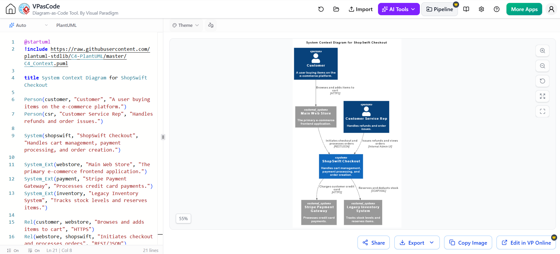
In the rapidly evolving landscape of software architecture, clarity is currency. The C4 model has emerged as the industry standard for visualizing software architecture because it scales from high-level context down to code-level details. This tutorial guides you through the creation of a System Context Diagram (Level 1) for a fictional microservice called ShopSwift, using PlantUML syntax within the Visual Paradigm environment.
We will explore how to define boundaries, identify actors, and map critical data flows. By the end of this guide, you will understand not just the syntax, but the architectural philosophy behind defining a system’s “black box” boundaries.
1. Defining the Scope: The System Context Diagram
The System Context Diagram is the highest level of the C4 hierarchy. Its primary goal is to show the system you are building (in this case, ShopSwift) and the people and other systems that interact with it. It answers the question: “How does this system fit into the wider world?”
For ShopSwift, we are building a checkout microservice. To model this effectively, we must identify three distinct categories of entities:
- People (Actors): The humans interacting with the system.
- The System Under Construction: ShopSwift itself.
- External Systems: Other applications that ShopSwift must talk to.
Step 1: Identifying the Actors and Systems
Before writing a single line of code, we must define our components:
- Customer: The primary user. They do not talk to ShopSwift directly; they use the Main Web Store.
- Main Web Store: The frontend application. This is the trigger for our microservice.
- ShopSwift Checkout: The system we are designing. It handles cart logic, payments, and orders.
- Stripe Payment Gateway: A third-party SystemExt (External System) responsible for financial transactions.
- Legacy Inventory System: Another SystemExt used to manage stock levels.
2. The PlantUML Implementation
Visual Paradigm supports “Diagram-as-Code,” allowing you to define architecture using text. We utilize the C4-PlantUML library to ensure our diagram adheres to the correct visual standards. Below is the code structure used to generate the ShopSwift context diagram.
@startuml
!include https://raw.githubusercontent.com/plantuml-stdlib/C4-PlantUML/master/C4_Context.puml

title System Context Diagram for ShopSwift Checkout

' --- 1. Define People ---
Person(customer, "Customer", "A user buying items on the e-commerce platform.")
Person(csr, "Customer Service Rep", "Handles refunds and order issues.")

' --- 2. Define The System ---
System(shopswift, "ShopSwift Checkout", "Handles cart management, payment processing, and order creation.")

' --- 3. Define External Systems ---
System_Ext(webstore, "Main Web Store", "The primary e-commerce frontend application.")
System_Ext(payment, "Stripe Payment Gateway", "Processes credit card payments.")
System_Ext(inventory, "Legacy Inventory System", "Tracks stock levels and reserves items.")

' --- 4. Define Relationships (Data Flows) ---
Rel(customer, webstore, "Browses and adds items to cart", "HTTPS")
Rel(webstore, shopswift, "Initiates checkout and processes orders", "REST/JSON")
Rel(shopswift, payment, "Charges customer credit card", "HTTPS")
Rel(shopswift, inventory, "Reserves and deducts stock", "SOAP/XML")
Rel(csr, shopswift, "Issues refunds and views orders", "Internal Admin UI")

@enduml
Breaking Down the Syntax
Notice the specific keywords used in the code above. In the C4 model, the distinction between System and SystemExt is critical.
Person: Represents human actors. Note that the Customer interacts with the Web Store, not the Checkout system directly. This is a common architectural pattern where the checkout logic is decoupled from the browsing experience.System: Represents the software system you are currently building (ShopSwift).SystemExt: Represents systems outside your direct control or scope, such as the Legacy Inventory System or Stripe.Rel: Defines a relationship (a “Rel” or “Relationship”). The fourth argument in the command (e.g., “HTTPS”) defines the Technology/Protocol used for the communication.
3. Leveraging AI for Architecture
One of the powerful features of the Visual Paradigm workflow is the integration of AI assistants. Instead of manually typing syntax, you can describe your architecture in natural language.
Workflow Example:
- Open the Visual Paradigm AI Assistant.
- Prompt: “Generate a C4 Context PlantUML script for an e-commerce checkout system. Include a Customer, a Main Web Store, the Checkout System, a Stripe Payment Gateway, and a Legacy Inventory System. Define the relationships.”
- The AI generates the code block provided above, which you can then refine and render instantly.
4. Analyzing the Data Flows
The strength of the System Context Diagram lies in the relationships (arrows) between the boxes. Let’s analyze the specific flows for ShopSwift:
- Customer to Web Store (HTTPS): The user experience is mediated by the frontend. The checkout system is a “black box” to the user.
- Web Store to ShopSwift (REST/JSON): This indicates a modern, API-driven architecture. The Web Store triggers the checkout process via a RESTful API.
- ShopSwift to Payment (HTTPS): A secure connection is used to handle sensitive financial data.
- ShopSwift to Inventory (SOAP/XML): Pro Tip: Note the technology change here. The internal API is REST, but the connection to the Legacy Inventory System is SOAP/XML. This is a classic example of a “Strangler Fig” pattern or legacy integration, where a modern system must talk to old tech using older protocols.
- CSR to ShopSwift (Internal Admin UI): This shows that customer service reps have direct access to the system for administrative tasks like refunds.
Conclusion
By defining the System Context Diagram first, we establish the boundaries of the ShopSwift microservice. We have identified that it relies on a legacy inventory system and a third-party payment gateway. This high-level view is essential before diving into the Container Diagram (Level 2), where we would break down the ShopSwift system into its internal databases and services.
Using tools like Visual Paradigm with PlantUML allows architects to iterate quickly, ensuring that the system boundaries and integration points are clear before a single line of business logic is written.
 vpadmin
- November 2, 2026
