


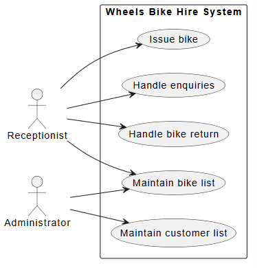
In the realm of software engineering and system analysis, Use Case diagrams serve as the bridge between abstract user needs and concrete technical requirements. They provide a visual representation of how actors interact with a system to achieve specific goals. Today, we will dissect a classic example: the Wheels Bike Hire System. By analyzing this system, we will explore the fundamental principles of actor identification, use case definition, and the crucial relationships that bind them together.
1. The Foundation: Actors and Scope
Every use case model begins with defining the system boundary and identifying the actors. Actors represent external entities—users, other systems, or hardware—that interact with the software. In the context of the Wheels Bike Hire System, we have identified two primary actors:
- Receptionist: The primary user who manages daily operations, such as renting bikes and handling customer inquiries.
- Administrator: The user responsible for system maintenance, such as updating inventory and customer data.
The System Boundary is the rectangle that encapsulates all use cases, clearly separating internal system logic from external interactions. In our model, everything inside the box belongs to the “Wheels Bike Hire System.”
2. Defining the Use Cases
Use cases are specific functions or services provided by the system. Based on the scenario, we have mapped out the following core functionalities:
- Maintain bike list: Adding new bikes or removing damaged ones.
- Maintain customer list: Storing and updating customer profiles.
- Handle enquiries: Providing information about availability and costs.
- Issue bike: The process of renting a bike to a customer.
- Handle bike return: Processing the return of a rented bike.
3. Visualizing with PlantUML
To accurately document this architecture, we use the PlantUML syntax. This text-based language allows us to generate diagrams programmatically. Below is the code that generates the basic structure of the Wheels Bike Hire System, defining the actors and their direct associations with the use cases.
@startuml
left to right direction
actor "Receptionist" as rec
actor "Administrator" as adm
rectangle "Wheels Bike Hire System" {
  usecase "Maintain bike list" as UC1
  usecase "Maintain customer list" as UC2
  usecase "Handle enquiries" as UC3
  usecase "Issue bike" as UC4
  usecase "Handle bike return" as UC5
}
rec --> UC1
rec --> UC3
rec --> UC4
rec --> UC5
adm --> UC1
adm --> UC2
@enduml
4. Advanced Modeling: Relationships
A static diagram showing only associations is useful, but a robust system model requires understanding how use cases interact with each other. We utilize two primary relationships in UML: Include and Extend.
Include Relationships («include»)
An include relationship indicates that one use case (the base) always incorporates the behavior of another use case (the included). It represents mandatory sub-functionality.
- Issue bike «include» Handle enquiries: You cannot issue a bike without first handling enquiries regarding availability and cost. This is a mandatory step.
- Handle bike return «include» Print receipt: Returning a bike often necessitates printing a receipt, especially for late or damaged returns.
Extend Relationships («extend»)
An extend relationship indicates that a use case (the extending) adds behavior to another use case (the base) under specific conditions. It represents optional or conditional functionality.
- Issue bike «extend» Maintain customer list: While issuing a bike is the primary goal, it might extend the functionality of maintaining a customer list if a new customer needs to be registered during the transaction.
When modeling these relationships, remember that the arrow direction is critical. For include and extend, the arrow always points from the extending/base use case to the included/extended use case.
5. Conclusion
By structuring the Wheels Bike Hire System using these principles, we create a clear blueprint for developers and stakeholders. The separation of concerns between the Receptionist and Administrator, combined with the logical grouping of actions through include/extend relationships, ensures that the system is both robust and easy to understand. Mastering these diagrams is the first step toward building scalable, user-centric software architectures.
 vpadmin
- October 30, 2026
