


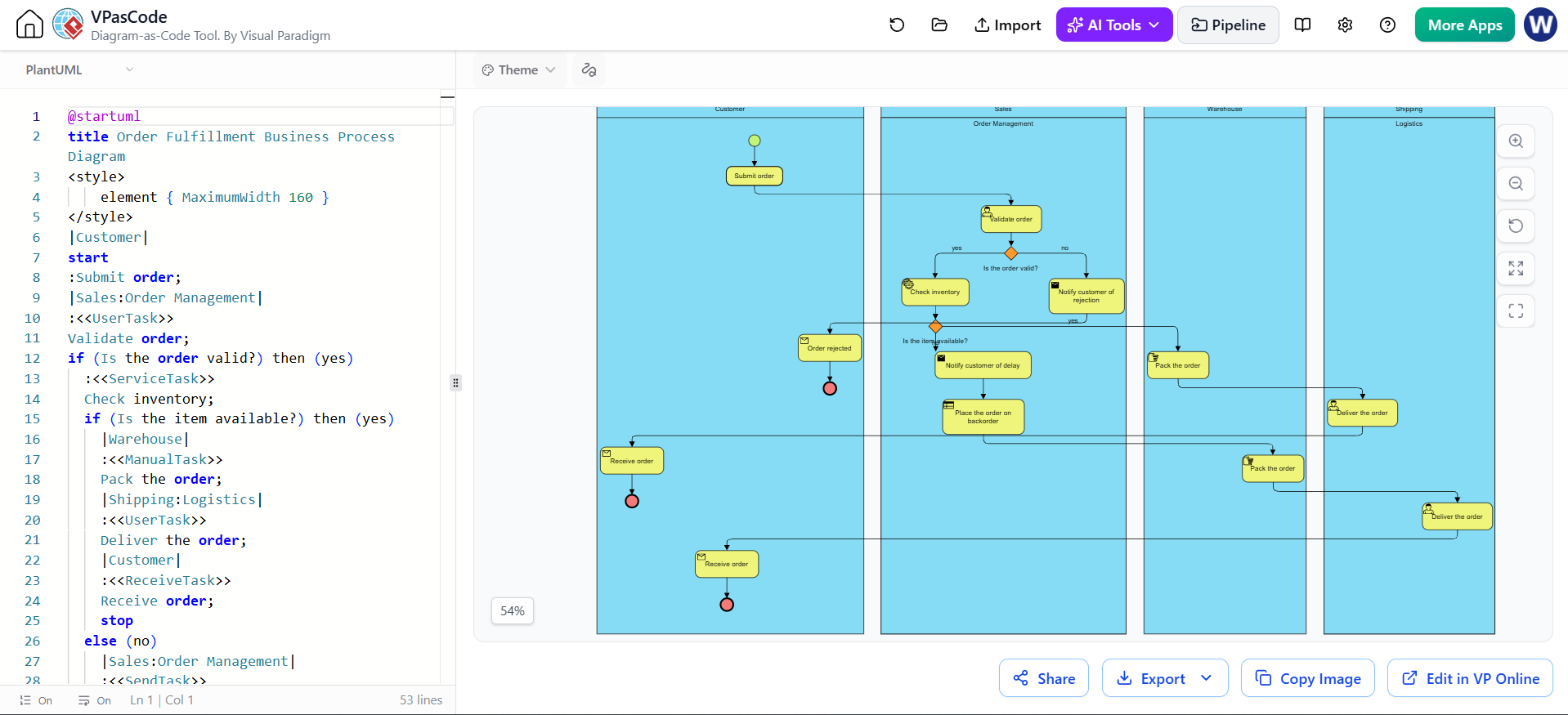
In the world of Business Process Management (BPM), clarity is currency. When you need to visualize complex interactions between different departments—such as Sales, Warehouse, and Logistics—you need a notation that handles “swimlanes” and “message flows” with precision. This tutorial explores how to use VPasCode (Visual Paradigm’s diagram-as-code tool) to generate a robust Order Fulfillment process, transforming text-based logic into a professional BPMN 2.0 diagram.
Understanding the Architecture: Pools and Lanes
The fundamental challenge in modeling business processes is determining the scope. In the provided example, the system architecture is designed to show interactions between distinct organizational units. BPMN (Business Process Model and Notation) achieves this using Pools and Lanes.
- Pools: Represent the boundaries of the process. In our scenario, the “Customer” acts as an external entity (a separate pool), while the internal operations (Sales, Warehouse, Shipping) reside within the organization’s main pool.
- Lanes: These subdivide a pool to represent roles or departments. The code snippet explicitly defines lanes for
Sales,Warehouse, andShipping, ensuring that tasks like “Validate order” and “Pack the order” are correctly assigned to their respective domains.
Key Modeling Concepts in the Code
The text on the left side of the interface represents the PlantUML syntax used to drive the visual engine. Here is how the logic translates to the visual diagram:
- Collaboration Start: The process begins with a
:Submit order;task in the Customer lane. This is the trigger event. - Message Flows: Notice the lines crossing the boundary between the Customer pool and the Sales pool. In the code, these are represented by the flow of control from the customer’s task to the sales task. Visually, they appear as dashed lines (or solid lines in some BPMN styles depending on the theme), indicating communication between different pools.
- Gateways: The code uses
if (Is the order valid?)to create decision points (diamonds). This is a critical part of the logic that determines the path of the process flow. - Task Types: The code differentiates between
UserTask(human work),ServiceTask(automated work), andReceiveTask(waiting for input), ensuring the diagram accurately reflects the nature of the work.
Step-by-Step: Analyzing the Order Fulfillment Logic
Let’s walk through the specific logic defined in the code snippet to understand how the diagram is constructed.
1. The Validation Phase
The process moves from the Customer to the Sales department. The first critical decision is Validate order. The code snippet shows:
if (Is the order valid?) then (yes)
  Check inventory;
else (no)
  Notify customer of rejection;
This creates a branching path in the diagram. If the order is invalid, the process terminates with a rejection event (the red circle). If valid, it proceeds to check stock levels.
2. Inventory and Backorder Logic
The next gateway asks, Is the item available?. This is where the complexity of real-world logistics often arises. The code handles a “No” scenario by offering two distinct paths:
if (Is the item available?) then (yes)
  Pack the order;
else (no)
  Notify customer of delay;
  Place the order on backorder;
In the visual output, this logic creates a split where the flow can either continue to the Warehouse (for packing) or move to a notification task in the Sales lane before looping back or ending.
3. Fulfillment and Handover
Once the item is packed in the Warehouse lane, the process must hand off to Shipping. This is modeled using Message Flows that cross the lane boundaries within the pool. Finally, the order is delivered, and the Customer receives it, completing the cycle.
Advanced Syntax: Customizing Your Diagram
One of the most powerful features of VPasCode is the ability to inject custom styles directly into the PlantUML code. In the example provided, we see a specific style block that controls the layout:
This CSS-like block forces every element in the diagram to have a maximum width of 160 pixels, ensuring that the text doesn’t overflow and the diagram remains clean and readable.
Conclusion
By using VPasCode, you move beyond the limitations of drag-and-drop interfaces. You can version control your processes, iterate through complex logic with code, and instantly generate accurate BPMN diagrams. Whether you are modeling a simple approval workflow or a multi-departmental supply chain, the “diagram-as-code” approach offers precision and scalability that traditional tools often lack.
 vpadmin
- November 4, 2026
