


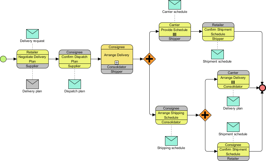
In the realm of complex business systems, understanding how independent entities interact without a central controller is crucial. This tutorial dissects the MIS Choreography Diagram shown above. We will explore how the Retailer, Consignee, Supplier, and Carrier collaborate to execute a delivery lifecycle. This diagram represents a High-Level Choreography model, utilizing the BPMN (Business Process Model and Notation) standard to visualize the exchange of messages between participants.
Understanding the Core Components
Before tracing the flow, it is essential to understand the building blocks used in this visual model. Unlike a standard flowchart, a choreography diagram focuses on the interaction between parties rather than the internal logic of a single one.
1. The Participants (Swimlanes)
The diagram is organized into vertical columns, often referred to as lanes or pools. In this MIS example, we see distinct roles:
- Retailer: The entity initiating the request for goods.
- Consignee/Supplier: The entity responsible for holding the stock and dispatching it.
- Consolidator: An intermediary role that groups shipments for efficiency.
- Carrier: The logistics provider responsible for physical transport.
Each box in the diagram is a Participant box. Notice how the grey headers (e.g., “Consignee”) group the yellow activities below them, indicating that these actions belong to that specific role.
2. The Interaction Flow
The process is driven by a sequence of events. The green circle on the far left represents the Start Event. From there, the process moves horizontally, indicating the flow of time and information.
Tracing the Delivery Lifecycle
Let’s walk through the logic of the diagram step-by-step, moving from the initial request to the final confirmation.
Phase 1: Negotiation and Planning
The journey begins with the Retailer. The first action is Negotiate Delivery Plan. This is a critical business decision where the retailer agrees on terms with the Supplier.
- Input: The process is triggered by a Delivery Request message (represented by the teal envelope at the top).
- Output: Once negotiated, the retailer produces a Delivery Plan (represented by the grey envelope at the bottom).
Phase 2: Dispatch Confirmation
Once the plan is set, the Consignee (acting on behalf of the Supplier) must validate the logistics. They perform the Confirm Dispatch Plan task.
- This action generates a Dispatch Plan, which is passed to the next phase. This ensures that the physical inventory is ready to be moved.
Phase 3: The Decision Fork
As the flow moves to the Consignee arranging the delivery, a critical branching point occurs. The diamond shape with the Orange Plus (+) sign is a Parallel Gateway.
This symbol dictates that the process does not stop here; instead, it splits into multiple concurrent paths. The system is essentially saying, “The delivery arrangement can happen in two ways simultaneously.”
Advanced Logic: Parallel Branching
This is the most complex part of the MIS Choreography. The parallel gateway splits the flow into an Upper Path and a Lower Path, which eventually merge back together.
The Upper Path: Direct Carrier Interaction
In this branch, the Carrier and Retailer engage in a direct scheduling loop:
- The Carrier performs Provide Schedule III (likely a specific type of logistics schedule).
- The Retailer responds by performing Confirm Shipment Schedule.
- This exchange generates a Shipment Schedule message.
The Lower Path: Consolidated Logistics
Simultaneously, the lower branch handles the consolidation of goods:
- The Consignee performs Arrange Shipping Schedule.
- This triggers a parallel split again (the second orange diamond).
- This results in two sub-tasks:
- The Carrier/Consolidator performs Arrange Delivery III.
- The Consignee/Retailer performs Confirm Shipment Schedule.
Merging the Flows
At the end of the diagram, both the upper and lower paths converge at a Red Circle. This is the End Event. In BPMN, the Parallel Gateway ensures that the process only reaches this end state once all parallel branches have completed their tasks. The system waits for both the direct carrier schedule and the consolidated arrangement to be finalized before marking the choreography as complete.
Technical Modeling Best Practices
When recreating this architecture using tooling like Visual Paradigm or AI-assisted modeling environments, keep these structural rules in mind:
- Swimlane Alignment: Ensure that every task (yellow box) is strictly contained within its respective participant lane. A task should never float in the white space between lanes.
- Message Objects: Use the envelope icon to clearly distinguish between the Process (the action) and the Artifact (the document or data). In this diagram, the “Delivery Request” is the artifact that triggers the start.
- Parallel Gateways: The ‘+’ symbol is specific to parallel execution. If the logic were sequential (one after the other), you would use a diamond with no symbol or a different logic gate.
Conclusion
The MIS Choreography Diagram effectively visualizes a multi-party logistics agreement. By breaking down the process into negotiation, dispatch, and parallel scheduling, it provides a clear blueprint for developers and business analysts to implement the underlying system logic. Whether you are using Python for backend logic or BPMN tools for process design, this diagram serves as the single source of truth for the delivery interaction.
 vpadmin
- November 18, 2026
