


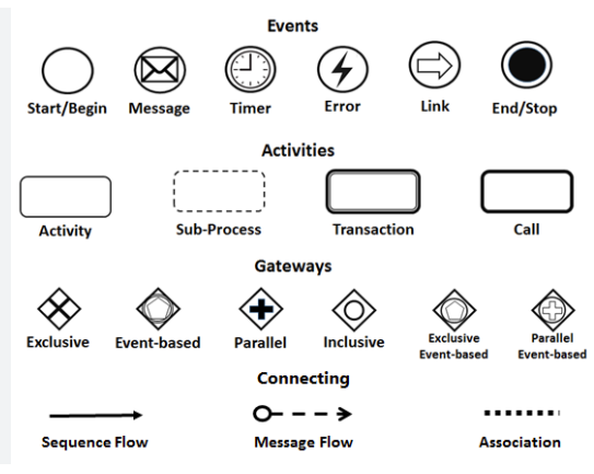
Business Process Model and Notation (BPMN 2.0) is the universal standard for visualizing business processes. It serves as a bridge between business stakeholders and technical developers, allowing complex logic to be translated into diagrams that are both human-readable and machine-executable.
Using tools like Visual Paradigm with AI-assisted modeling, you can construct robust process flows. This guide breaks down the core building blocks—Events, Activities, Gateways, and Connectors—based on standard BPMN specifications.
1. Events: The Triggers and Outcomes
In BPMN, Events are represented by circles. They define “what happens” rather than “what is done.” Events are the catalysts that start a process or the results that conclude it.
The Lifecycle of an Event
- Start Events (Thin Border): These mark the beginning of a process. They wait for a trigger (like a form submission or a timer) before the process flow begins.
Example: “Leave Application Submitted” - Intermediate Events: These occur during the process. They can be a Message (waiting for an email), a Timer (waiting for a date), or an Error (handling an exception). The Link event is used to jump to another part of the diagram.
- End Events (Thick Border): These signify the termination of the process. The process stops once the flow reaches this point.
Example: “Order Delivered”
2. Activities: The Work Units
Activities are the actual work performed within a process. They are represented by rounded rectangles and define the “doing” part of the diagram.
Types of Activities
- Task (Activity): The smallest unit of work. It is atomic and cannot be broken down further within the context of that specific diagram.
Example: “Evaluate Application” - Sub-Process: A complex activity that contains its own internal logic. It is represented by a rounded rectangle with a dashed border or a plus (+) sign. This allows you to hide complexity by collapsing it into a single box and expanding it only when necessary.
- Transaction: A special type of sub-process that ensures data integrity. If the transaction fails, the system rolls back the changes, ensuring the process remains consistent.
- Call Activity: Used to reference a reusable process or a sub-process defined in another diagram. It allows for modular design.
3. Gateways: The Decision Makers
Gateways are diamonds that control the flow of the process. They determine which path the process takes next based on conditions or logic.
Understanding Logic Types
- Exclusive Gateway (XOR): Marked with an X. It forces the process to choose one path out of several.
Logic: “Approved?” (Yes OR No). - Parallel Gateway (+): Marked with a +. It splits the flow into multiple simultaneous paths that execute at the same time. It also acts as a barrier where all incoming paths must finish before the process continues.
- Inclusive Gateway (OR): Marked with an OR symbol. It allows for one or more paths to be taken based on conditions.
- Event-Based Gateway: Marked with an event icon inside. The process waits for an external event to occur (e.g., “Payment Received”) before proceeding down a specific path.
4. Connecting Objects: The Flow Logic
Connectors define the relationship between elements. Using the wrong connector is a common error that breaks BPMN semantics.
Sequence vs. Message Flow
- Sequence Flow (Solid Line): Represents the order of activities inside a single participant or pool. It shows the immediate next step in the workflow.
- Message Flow (Dashed Line): Represents communication between different participants or pools. For example, a manager sending a request to the HR department.
- Association (Dotted Line): Links data, text annotations, or artifacts to elements without implying a flow of control.
Best Practices for Modeling
To create professional, executable diagrams:
- Keep it Simple: Don’t mix too many gateways in one spot. Use Exclusive gateways for decisions and Parallel gateways for concurrent tasks.
- Modularize: Use Sub-Processes to break down complex logic into manageable chunks.
- Visual Consistency: Ensure Start and End events are clearly distinguishable (thin vs. thick borders) to guide the reader’s eye through the process lifecycle.
 vpadmin
- November 5, 2026
